Draw Mohr Circles for 3d Stress States
This chapter is from the book
i.fifteen Mohr'south Circles in Three Dimensions
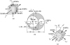
Consider a wedge shown in Fig. 1.25a, cut from the cubic element subjected to triaxial stresses (Fig. one.22a). The only stresses on the inclined x' face (parallel to the z axis) are the normal stress s x' and the shear stress t x'y' interim in the ten'y' aeroplane. Inasmuch as the foregoing stresses are determined from force equilibrium equations in the x'y' plane, they are independent of the stress s iii. Thus, the transformation equations of plane stress (Sec. 1.ix) and Mohr'due south circle can be employed to obtain the stresses s x' and t 10'y' . The foregoing decision is also valid for normal and shear stresses acting on inclined faces cut through the element parallel to the x and y axes.
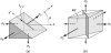
Figure ane.25 Triaxial state of stress: (a) wedge; (b) planes of maximum shear stress.
The stresses acting on elements oriented at various angles to the principal axes tin can exist visualized with the aid of Mohr'due south circle. The cubic element (Fig. ane.22a) viewed from three dissimilar directions is sketched in Figs. 1.26a to c. A Mohr's circle is drawn corresponding to each projection of an element. The cluster of three circles represents Mohr'due south circles for triaxial stress (Fig. 1.26d). The radii of the circles are equal to the maximum shear stresses, as indicated in the figure. The normal stresses interim on the planes of maximum shear stresses accept the magnitudes given by the abscissa as of the centers of the circles.
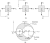
Figure 1.26 (a–c) Views of elements in triaxial stresses on different principal axes; (d) Mohr's circles for three-dimensional stress.
The largest shear stresses occur on planes oriented at 45° to the principal planes. The shear stress is a maximum located as the highest bespeak on the outer circumvolve. The value of the absolute maximum shearing stress is therefore
Equation ane.45
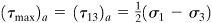
acting on the planes that bisect the planes of the maximum and minimum principal stresses, every bit shown in Fig. 1.25b. It is noted that the planes of maximum shear stress may besides be ascertained by substituting north ii = 1 – 50 2 – thou ii into Eq. (1.38b), differentiating with respect to l and m, and equating the resulting expressions to zero (Prob. one.fourscore).
Determining the accented value of maximum shear stress is pregnant when designing members made of ductile materials, since the strength of the material depends on its ability to resist shear stress (Sec. 4.half-dozen). Obviously, as far every bit the stress magnitudes are concerned, the largest circle is the almost significant one. However, all stresses in their various transformations may play a role in causing failure, and information technology is normally instructive to plot all iii chief circles of stress, as depicted in the figure. An case of this type occurs in thin-walled pressurized cylinders, where due south q = s ane, s a = s two, and due south r = due south 3 = 0 at the outer surface (Table one.i). It is as well interesting to note that, in special cases, where two or all primary stresses are equal, a Mohr's circle becomes a point.
Equations of Three Mohr'south Circles for Stress
Information technology has been demonstrated that, given the values of the main stresses and of the direction cosines for any oblique plane (Fig. 1.22b), the normal and shear stresses on the plane may be ascertained through the application of Eqs. (1.37) and (ane.38). This may also exist accomplished by means of a graphical technique due to Mohr [Refs. 1.x through 1.12]. The latter procedure was used in the early history of stress assay, but today information technology is employed only as a heuristic device.
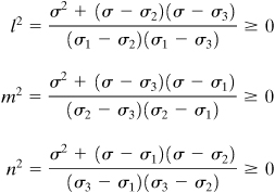
In the following discussion, we demonstrate that the aforementioned equations together with the relation l two + m 2 + n 2 = ane are represented by three circles of stress, and the coordinates ( south , t ) locate a signal in the shaded area of Fig. i.26d [Ref. 1.13]. These simultaneous equations are
Equation a
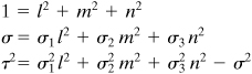
where l 2  0, m two 0, and northward two 0. Solving for the management cosines, results in
Equation 1.46
Inasmuch equally south ane > south 2 > due south 3, the numerators of Eqs. (1.46) satisfy
Equation b
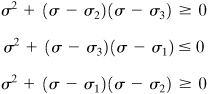
as the denominators of Eqs. (1.46) are ( s ane – southward 2) > 0 and ( s 1 – due south three) > 0, ( s 2 – due south iii) > 0 and ( s 2 – s 1) < 0, ( south iii – s one) < 0 and ( s 3 – southward two) < 0, respectively.
Finally, the preceding inequalities may be expressed as follows
Equation 1.47
Equations (ane.47) stand for the formulas of the three Mohr's circles for stress, shown in Fig. ane.26d. Stress points ( s , t ) satisfying the equations for circles centered at C one and C ii lie on or outside circles, but for the circumvolve centered at C 3 lie on or inside circumvolve. We conclude therefore that an open-door state of stress must lie on Mohr's circles or within the shaded area enclosed by these circles.
Example 1.8. Analysis of Three-Dimensional Stresses in a Member
The state of stress on an element of a structure is illustrated in Fig. 1.27a. Using Mohr's circumvolve, decide (a) the principal stresses and (b) the maximum shearing stresses. Prove results on a properly oriented element. As well, (c) utilise the equations developed in Section 1.xiv to calculate the octahedral stresses.
Effigy 1.27 Example ane.8. (a) Element in three-dimensional stress; (b) Mohr's circles of stress; (c) stress element for  .
.
Solution
- First, Mohr'due south circle for the transformation of stress in the xy plane is sketched in the usual manner equally shown, centered at C 2 with bore A two A 3 (Fig. ane.27b). Side by side, we consummate the iii-dimensional Mohr'south circle by drawing ii additional circles of diameters A 1 A 2 and A 1 A iii in the effigy. Referring to the circumvolve, the master stresses are s 1 = 100 MPa, due south 2 = xl MPa, and s 3 = –lx MPa. Angle
 , as tan
  . The results are sketched on a properly oriented element in Fig. 1.27c.
 -
The absolute maximum shearing stress, point B 3, equals the radius of the circle centered at C three of diameter A 1 A 3. Thus,

The maximum shearing stress occurs on the planes 45° from the y' and z faces of the element of Fig. 1.27c.
-
The octahedral normal stress, from Eq. (1.44), is

The octahedral shearing stress, using Eq. (ane.43), is

Comments A comparison of the results (encounter Fig. 1.27b) shows that
| due south oct < s 1 | and | t october < ( t max) a |
That is, the maximum chief stress and accented maximum shear stress are greater than their octahedral counterparts.
Source: https://www.informit.com/articles/article.aspx?p=1729271&seqNum=15
0 Response to "Draw Mohr Circles for 3d Stress States"
Post a Comment